1.Application Background
A mine in Pakistan encountered difficulties about community environmental constraints during the development of the vertical shaft.
Vertical shaft parameters: diameter=2m, depth=100m, the shaft has been drilled through the underground to be used as a wind inlet.
Shaft stratum: tight sandstone, limestone, etc. The maximum uniaxial compressive strength of the rock is about 80 MPa.
Environmental restrictions: Due to the environmental constraints of the ground community, it is not allowed to blast, it is impossible to use the traditional drilling and blasting method. Therefore, the solution is needed in this case.
2.Solution
General sequence for the normal construction of shafts is: top-down tunneling. When the wellbore reaches a certain height, the wall is built up down-top, and the tunneling and wall-laying alternate. The process sequence of each section is drilling and blasting firstly, then load out the gangue and rock, and finally build the wall. Due to the limitations of the community environment, it is not possible to use the blasting tunneling, so it is recommended to use the raise boring machine process for vertical shaft development.
3.Construction Process
The raise boring machine construction process includes pilot hole drilling and reaming drilling. That is, first drill into the positive guide hole, and then reverse counter-reaming, as shown in Figure 1.
-and-reverse-expansion-hole-(right)-Helius-Tech-Joy.png)
Figure 1 Schematic diagram of drilling process for positive pilot hole (left) and reverse expansion hole (right)
The principle of the raise boring machine process is to drive the hydraulic motor via the motor of the drilling machine. The hydraulic motor drives the power unit, and torque is transmitted to the drilling tool system via hydraulic power, which drives the drill pipe and the drill bit to rotate. The hob on the drill bit is under the action of the drilling pressure, pure rolling and micro-slip along the working face of the rock at the bottom of the well. At the same time, the axial pull and pressure generated by the main cylinder also pass through the power head, and the drill pipe acts on the drill bit, so that the hob of the drill bit rolls under the action of the drilling pressure, generating an impact load, causing the hob teeth to impact and squeeze the rock. Pressing and shearing, breaking the rock.
For the pilot hole drilling, the broken rock cuttings are flushed by the circulating circulating washing fluid when the guiding hole is drilled, and the cuttings are lifted from the washing fluid to the outside of the borehole along the annular space between the drill pipe and the hole wall (see in Figure 2).
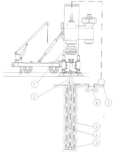
Figure 2 Raise Boring Machine Positively Hole Guiding Process
1-power head 2-drill rod 3-channel drill bit 4-mud from mud pump 5-loaded slag mud returned from annular space 6-mud circulation tank 7-mud pump
For raise boring machine drilling and tunneling, the rock debris fall directly into the lower roadway by their own weight, and then cleaned out by the mucking machine or other means (as shown in Figure 3).
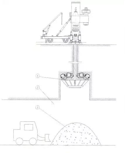
Figure 3 Raise Boring Machine Negatively Hole Reaming Process
In this example, ZFY2.5/400 (LM-400) anti-drilling rig is used to drill, first drill 270mm guide hole until the guide hole drills through the lower roadway, then remove the guide hole drill bit, and connect the 2m diameter reaming drill bit. Then, expand the hole down-up.
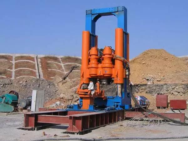
Figure 4 Raise Boring Machine
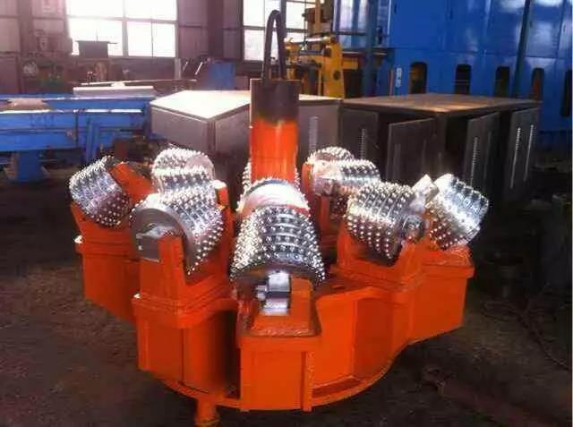
Figure 5 Reamer Bit
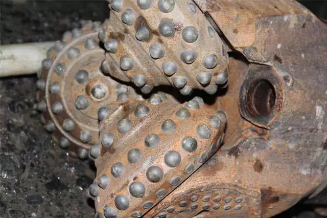
Figure 6 Hole Guiding Bit
Comparison Between Raise Boring Machine Technology and Traditional Blasting Construction Method
* Fast Speed
In the traditional construction method, it is necessary for the staff to carry out eye-catching, firing, slag, support and other operations in each section of the wellbore. Compared with the traditional construction method, the raise-boring machine technology has the following advantages, which can significantly improve the construction progress:
a. Eliminate the process of drilling and blasting.
b. The gangue discharging is handled by the transportation system of the lower roadway, especially when the shaft is deeper, the higher efficiency of raise boring machine.
c. As the personnel do not need to enter the shaft during the construction process, and the lithology which the shaft enters through is tight sandstone and limestone, it is not necessary to support the wall in time to prevent injury.
For example, in the North Second district of Gujiao Malan mine, design diameter is 3m, full height is 112m, with the application of raise boring machine technology, hole guiding time is 56.75h, hole expanding time is 61.5h, 118.26h in total. While compared with similar Zhenchengdi Mine, for 76m main coal bin, the construction operation time period is more than 2 months by using traditional drilling and blasting method.
* High Efficiency
Traditional construction methods of per shift includes drilling hole, blasting, supporting and gangue discharging, which involves exhausting physical labor and difficult working conditions. In the example above of Zhenchengdi Mine, more than 12 people per shift, and advancing speed is 2m per shift. While using raise boring machine, only 4-5 people per shift, advancing rate is 1m per hour. The labor intensity and construction conditions have been fundamentally improved.
* Ensure Safety
Because construction workers don’t enter the shaft, their safety is assured. The deflection rate is less than 1%, and greatly reduces damage for surrounding rocks, thus guarantee the safety.
* Low Cost
Reverse drilling can save a lot of material cost, and personnel costs are lower than traditional construction methods.
Model selection of raise boring machine in this case
* Choose hole drilling and expansion
Twice hole expansion is required if bigger diameter. In this project, the hole drilling depth, dip angle and diameter are confirmed. According to drilling hole parameters to select the reference table, for the project 2m excavation diameter deflection requirements of the project can be drilled once.
* Choose raise boring machine parameter
Although this project only drills 100m, considering actual application and other practical conditions, ZFY2.5/400 (LM-400) raise boring machine is chosen.
Technical parameters of ZFY2.5/400(LM-400) are as below
|
No. |
Description |
Unit |
Value |
|
1 |
Pilot hole diameter |
Mm |
270 |
|
2 |
Expansion hole diameter |
Mm |
1.4, 2.0, 2.5 |
|
3 |
Hole drilling depth |
Mm |
400 |
|
4 |
Shaft drilling speed |
Rpm |
2-21 |
|
5 |
Rated torque |
KN.m |
80 |
|
6 |
Maximum torque |
KN.m |
102 |
|
7 |
Maximum thrust |
kN |
2450 |
|
8 |
Expansion hole maximum tension |
kN |
3000 |
|
9 |
Drilling hole dip angle |
° |
60-90 |
|
10 |
Equipment weight(including carrier) |
t |
12.5 |
|
11 |
Equipment transportation size |
Mm |
3000*1750*1750 |
|
12 |
Equipment installation size |
Mm |
4850*1900*5250 |
|
13 |
Rod diameter*active length |
Mm |
Φ230*1000 |
|
14 |
Borehole deviation slope |
% |
≤1 |
|
15 |
Motor power |
kW |
168.5 |
|
16 |
Driven mode |
Hydraulic |
|
|
17 |
Application lithology (unidirectional compressive strength) |
MPa |
140.00 |
Technical Verification
Due to the maximum downwards thrust of the equipment is 2450KN, which is much larger than the thrust required for the drilling guide hole. To meet the engineering requirement, the expansion tension is verified below:
Actual working tension = Power head weight + hole drill bit weight + drill rod weight + maximum drilling pressure
Among which: power head and cylinder weight 40KN
Hole drill bit weight 25KN
Drill rod weight =155KG/m*400m*9.8N/KG=607.6KN
Maximum drilling pressure can refer to the following table, if speed is 1500mm/h, compressive strength is 80MPa, drilling pressure =477.5kN Then the actual work pulls =40+25+607.6+477.5=1150.1KN
Table 1 (D=2.0m) Relationship between drilling speed and drilling pressure
|
Rock compressive strength MPa |
Drilling speed=2500 mm/h |
2000 |
1500 |
1000 |
500 |
300 |
|
20 |
205.5kN |
183kN |
159.2kN |
|||
|
40 |
367.6kN |
318.4kN |
249.0kN |
|||
|
80 |
477.5kN |
389.9kN |
||||
|
120 |
649.8kN |
459.5kN |
||||
|
160 |
643.2kN |
498.3kN |
It is generally required that the actual working force should not exceed 60% of the maximum lift capacity of the rig. The maximum tensile force for hole expansion of ZFY2.5/400 (LM-400) in this example is 3000KN, and the actual working tensile force/maximum tensile ratio is 38%, which can meet the requirement.